click for larger image (20KB)
The present N6EX repeater uses the TK-931 as a 2 watt exciter for a 90 watt power amplifier. The original configuration (prior to the external 90 Watt PA) used the higher power TK-931HD as the complete transmitter (approximately 30 watts output). The modifications listed below pertain to the final configuration.
click for larger image (20KB) |
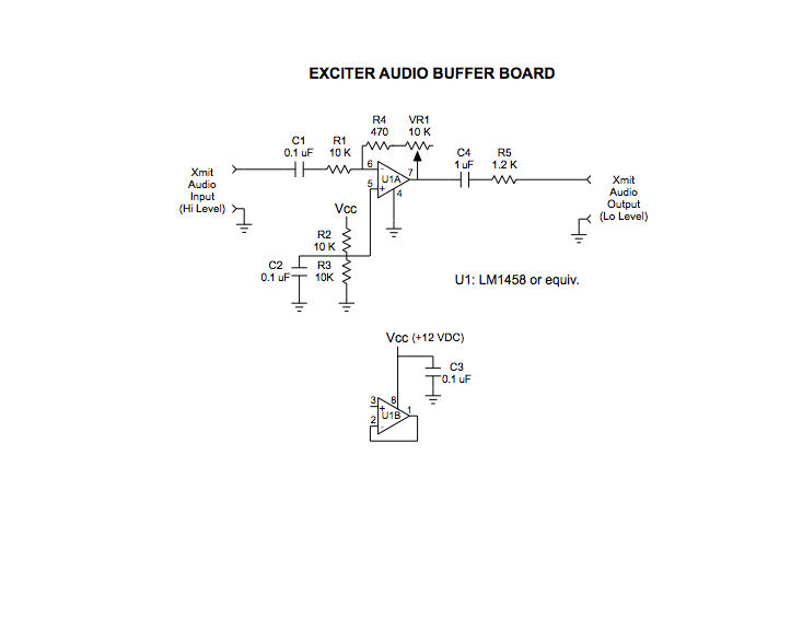
This is the schematic of a simple op-amp based circuit used to transform the high level audio signal produced by the controller to the low level required for the microphone input of the transmitter. The gain of the audio stage was chosen to take a 2 volt peak-to-peak, 1 kHz audio tone and drop it to a level necessary to produce a deviation of 2.5 kHz. |
 click for larger image (20KB) |
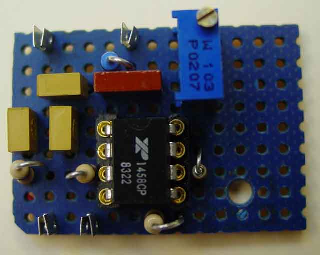
The above circuit was implemented on a copperclad perf-board. An LM1481 dual op-amp was used. Only one of the stages was needed. These low power amplifiers are readily available and run on a single supply. |
 click for larger image (56KB) |
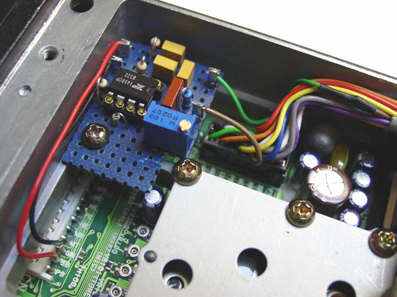
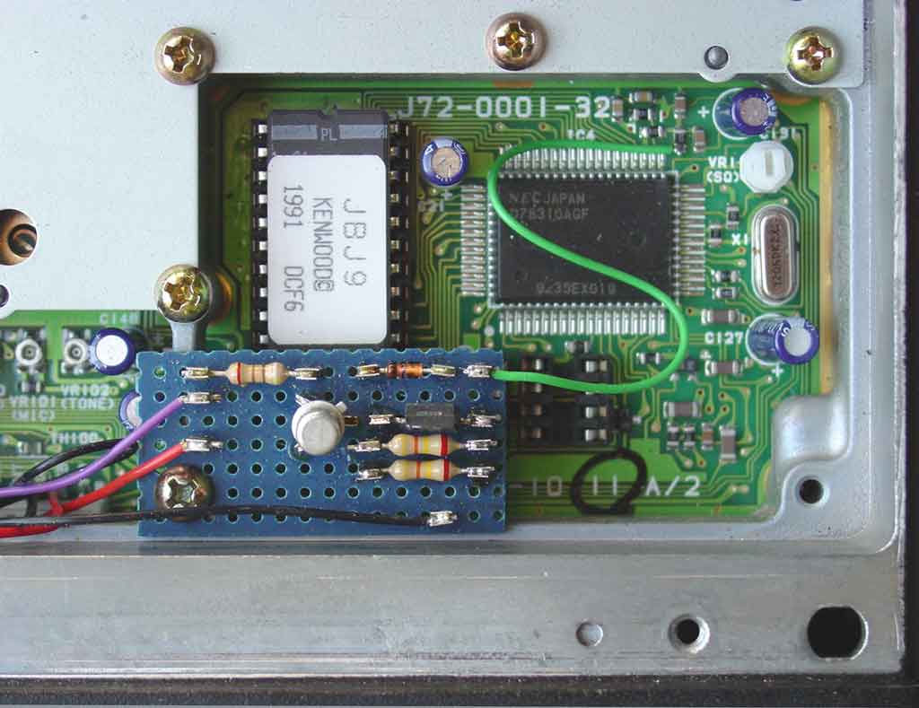
This photo shows the mechanical placement and electrical interconnection of the audio interface board within the exciter.
DC input to the audio interface board can be taken from the CN1 connector (connects front panel to main circuit board). Switched 13.8 VDC is on pin 2 (SB) and return is on pin 3 (GN). The audio connection is tapped into the cable running from the CN2 connector to rear panel connector (J4). The brown wire (MIC) is cut and the audio interface board is inserted at the break. The input of the audio board is connected to the brown wire running to the rear panel connector and the output of the audio board is connected to the wire running to CN2. |
 click for larger image (8KB) |
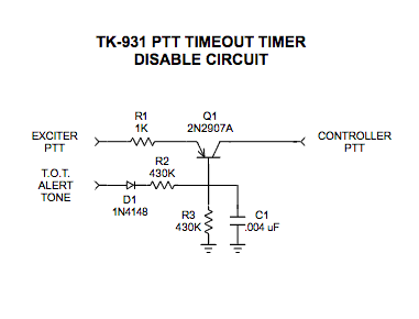
This is the schematic of the simple circuit that effectively disables the timeout timer of the TK-931. The PNP transistor conducts under normal conditions, allowing normal PTT action from the controller. When a timeout occurs, the circuit detects and filters the audio tone produced by the radio micro. When the filtered signal is applied to the base of the PNP transistor, it stops conducting, the PTT line is interrupted and the timer resets. The result is a brief (10 - 15 ms) interruption of transmission during the event. This short interruption sounds like brief click when listening to the output of the repeater. The diode and relatively large resistor values associated with the tone detection line are used to assure that the circuit has no impact to normal operation of the radio. The PNP transistor is placed inline with the PTT signal (transmit when pulled low) from the controller to the radio. |
 click for larger image (36KB) |
The above circuit was implemented on a small perf-board. A 2N2907A PNP transistor was used for the switching component. |
 click for larger image (60KB) |
This photo shows the mechanical placement of the TOT disable board within the exciter. It also shows the connection of the TOT warning tone sense signal from the radio to the TOT disable board. The sense line (green wire) connects to the "high" side of R31, which is the same point as pin 33 (ALT2) of the microcontroller. |
 click for larger image (36KB) |
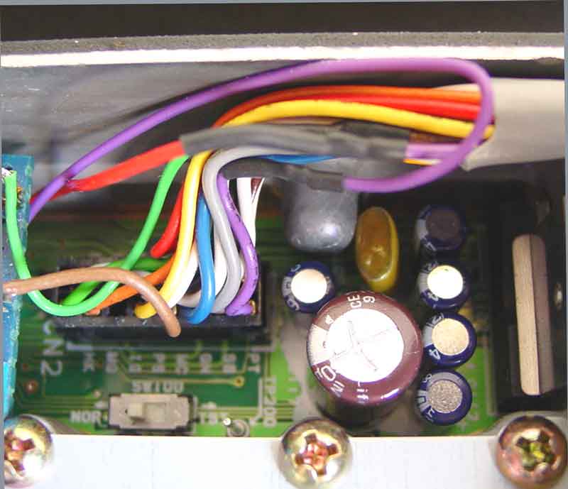
This photo shows the interconnection of the TOT disable board with the PTT circuitry within the radio. The purple wire (PTT) normally connected between CN2 and the rear panel connector (J4) is cut and the TOT disable board is injected between the two connectors. The purple wire running to J4 (Controller Side) is connected to the collector side of TOT disable board PNP transistor (red wire on TOT disable board). The PTT line on the CN2 connector (Exciter Side) is connected to the line (purple wire) going to the resistor feeding the emitter of the PNP transistor on the TPT disable board. Although not shown here, the ground connection for the TOT disable board connects to the same pin (pin 3 - GN) of the CN1 connector used to connect ground on the Audio Interface Board. |
 click for larger image (16KB) |
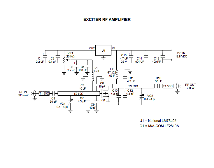
This is the schematic of the microstrip single stage RF amplifier. The amplifier is based on the M/A-Com LF2810A MOSFET (Thanks to Gary, WA6MEM for the parts). The transistor is actually a 10 watt, 28 volt part, but provides adequate gain for this application at 12 VDC. The amplifier provides greater than 40% efficiency at the desired output power. Trimmer capacitors are used for input and output matching. Output power is adjusted by a trimpot which sets the gate bias voltage. The amplifier was designed and fabricated as a joint project with Dave, WA6CGR. The amplifier was designed to provide similar functionality within the Kenwood TK-931 and Motorola Spectra 900 MHz radios. |
 click for larger image (8KB) |
This is the layout for the microstrip circuit board. The board material is 0.030 inch Duroid. The circuit board is compression soldered onto a similarly sized copper heat spreader. The board and spreader are milled and drilled to accept the flange-mount transistor. The spacing of board mounting holes matches the dimensions of the original Motorola power brick. |
 click for larger image (24KB) |
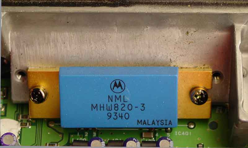
This photograph shows the original configuration of the TK-931. The Motorola MHW820-3 power module is mounted to the rear heatsink with two screws. The five pins of the module are soldered to the main circuit board. To begin the modification, the module needs to be unsoldered and removed from the radio. Retain the two mounting screws, as they will used later. |
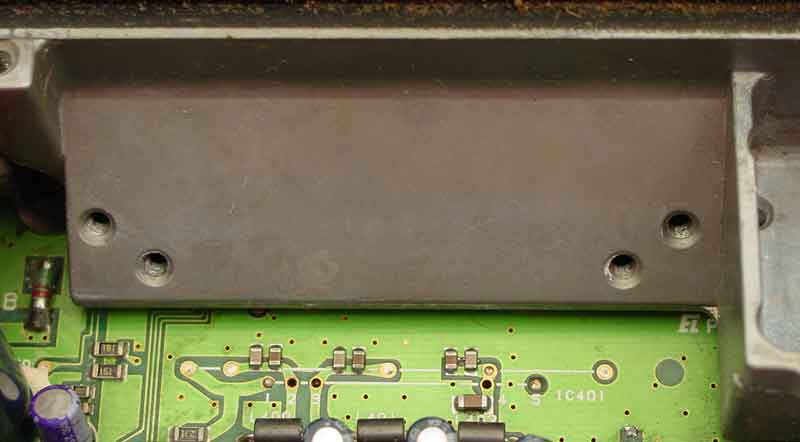 click for larger image (20KB) |
This photo shows the power brick mounting surface once the module has been removed. The heatsink mounting holes and the printed circuit board interface holes are clearly visible. |
 click for larger image (44KB) |
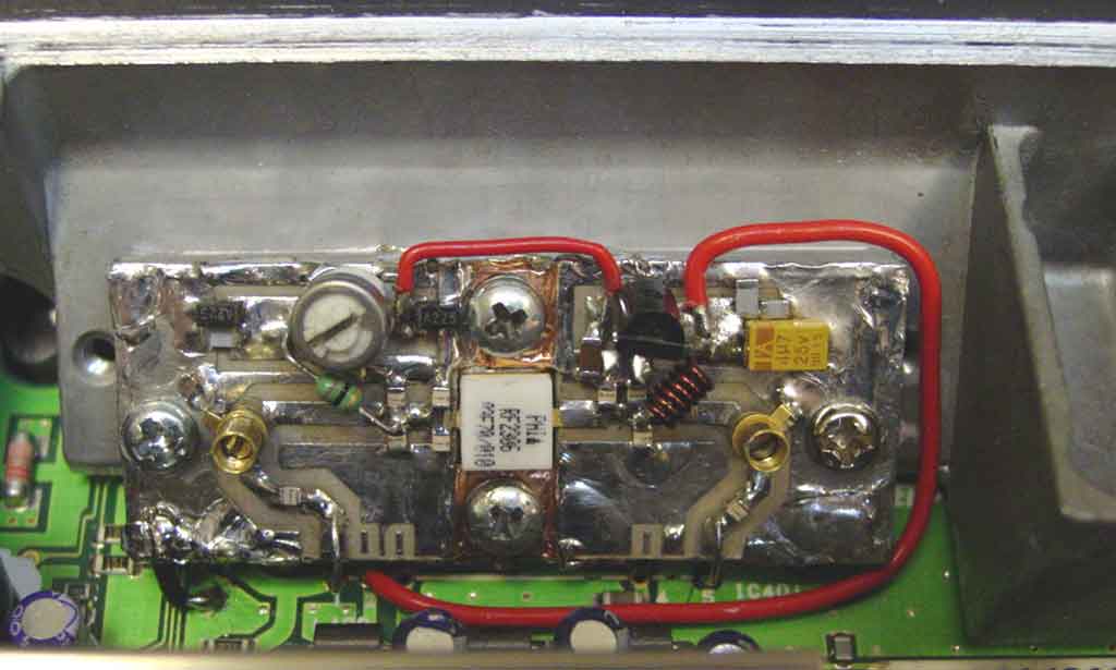
This photo shows the completed 2 watt amplifier installed in the radio. Heatsink compound should be applied between the module heat spreader and the radio heatsink. The input port of the amplifier should be connected to pin 1 of the PCB, the output to pin 5, and the +13.8 VDC input to pin 2. Additionally, a short jumper should be installed between the ground on the amplifier and the host radio. Once installed, the trimmer capacitors should be adjusted for maximum power and the trimpot adjusted for desired output power (nominally 2.0 watts). |
 click for larger image (16KB) |
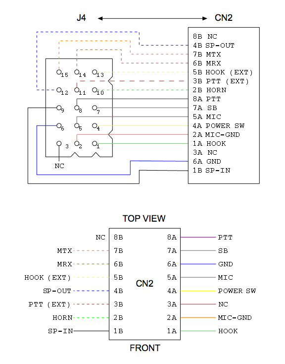
The J4 accessory connector is routed to an internal circuit board connector (CN2) via a multi-conductor cable. This diagram shows the factory wiring between the two connectors. The colors reflect the color coding or the wires in the cable. |
 click for larger image (16KB) |
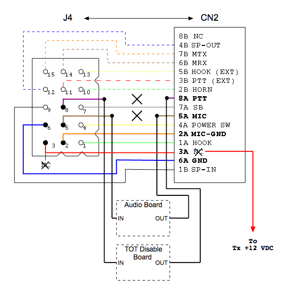
This is a modified diagram of the J4 to CN2 interconnections. It shows the modifications implemented to incorporate the audio interface board, TOT disable board and PA biasing line. It also highlights pins of the J4 connector which are used to connect the TK-931 Exciter to the Controller and External Power Amplifier. |
| J5 Pin | Signal |
|---|---|
| 2 | Ground (PA Bias Supply Return) |
| 3 | Transmit 12 VDC (PA Bias Supply) |
| 5 | Microphone Audio |
| 6 | Ground |
| 8 | PTT (Active Low) |
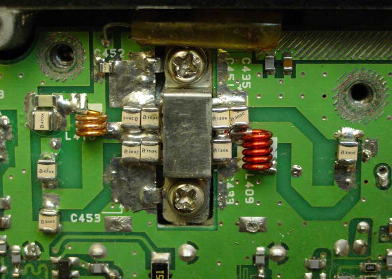 click for larger image (56KB) |
The components of the power amplifier section of the TK-931HD were changed to handle the harsher duty cycle conditions. All capacitors in the RF path were replaced with high quality ATC porcelain (B Size) components. Additionally, the choke coils were rewound from larger diameter solid wire. The limit on the wire size was dictated by the clearance available under the finals section shielding plate. |
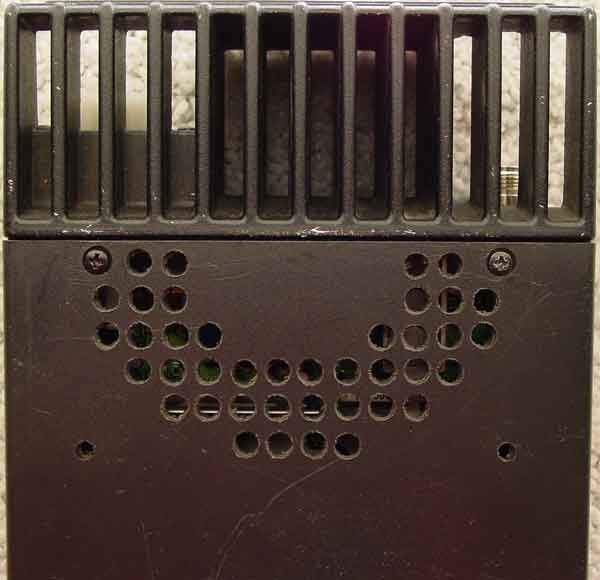 click for larger image (24KB) |
To improve cooling of the transmitter, a 4 inch muffin fan was added to the radio case. The fan was positioned to allow some air to flow into (and through) the rear section of the radio and some to flow across the heat sink. Holes were drilled in the top case to serve as the air inlet. |
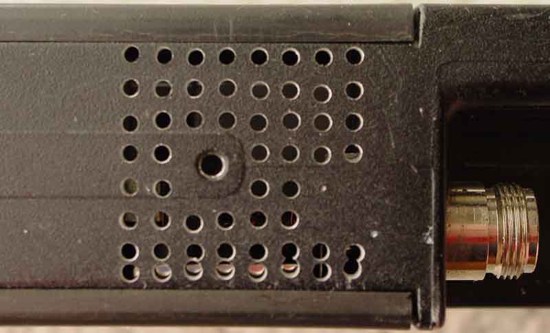 click for larger image (24KB) |
A matrix of small holes was drilled on the right side of the chassis at the back of the radio. This series of holes allows forced air to enter from the cover, flow over and around the transmitter section, and exit out the right side. |
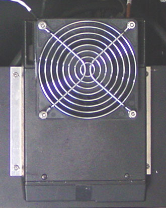 click for larger image (36KB) |
The photo shows the modified TK-931HD in service. The 4 inch muffin fan was installed on the top cover to blow air into and over the transmitter section. Although not clearly visible, a screen was installed between the fan and the top cover to prevent larger particles from being blown into the radio. The fan was actuated by the system controller. This limited fan operation to only times when the transmitter was active, thereby increasing its lifetime. |