Duplexer


Duplexer Photo 1
click for larger image (124KB)


Duplexer Photo 2
click for larger image (92KB)


Duplexer Photo 3
click for larger image (92KB)


The duplexer used on the N6EX repeater was derived from a Wacom receive preselector panel that was surplussed from commercial service. The panel originally comes with two pairs of dual bandpass filters (WP-4941-7941-2B). Each pair consists of a single pass cavity with adjustable coupling loops (about 0.2 dB to 3.0 dB) and a single pass/reject cavity (I.L. about 0.7 dB). Each of the filters is a four inch cavity and all are mounted on a 3U rack panel. The two filters in each pair come coupled with an 8.375" RG142 cable. While the filters where originally tuned for a 901.0 to 901.1 MHz passband and a 898 MHz reject, the filters are easily tunable for pass or reject in the 902 and 927 amateur repeater bands.

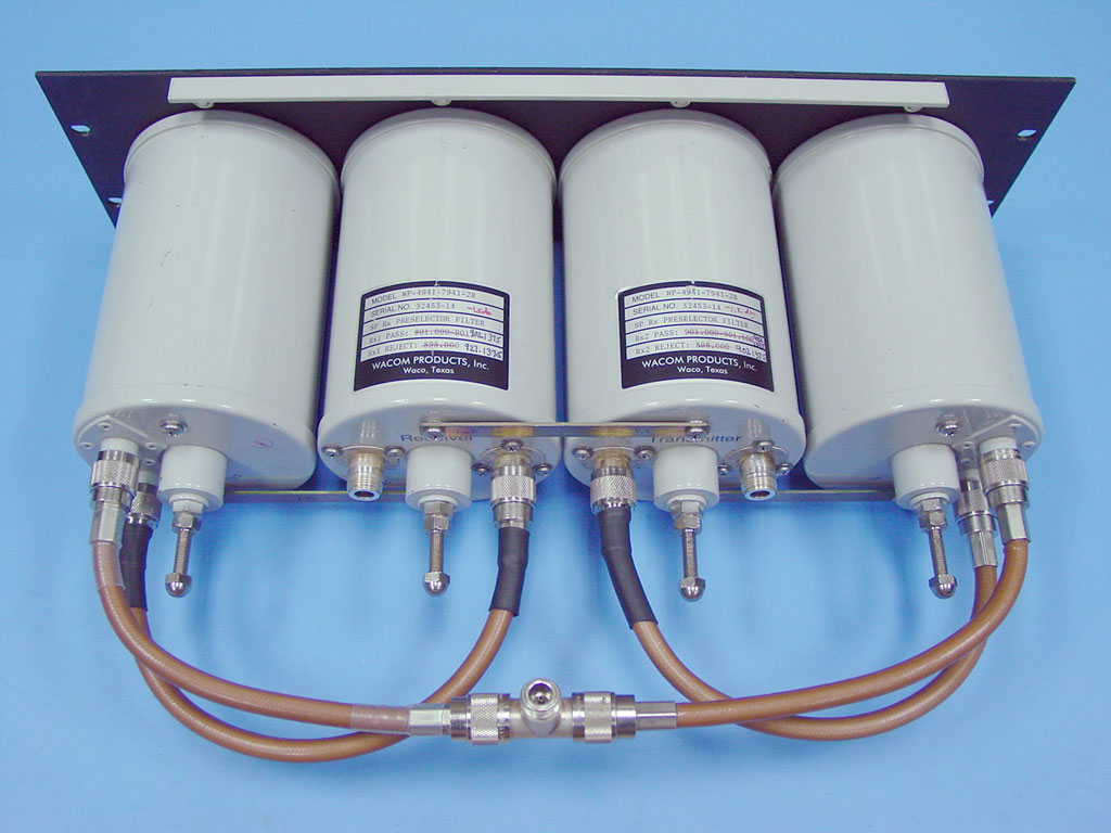
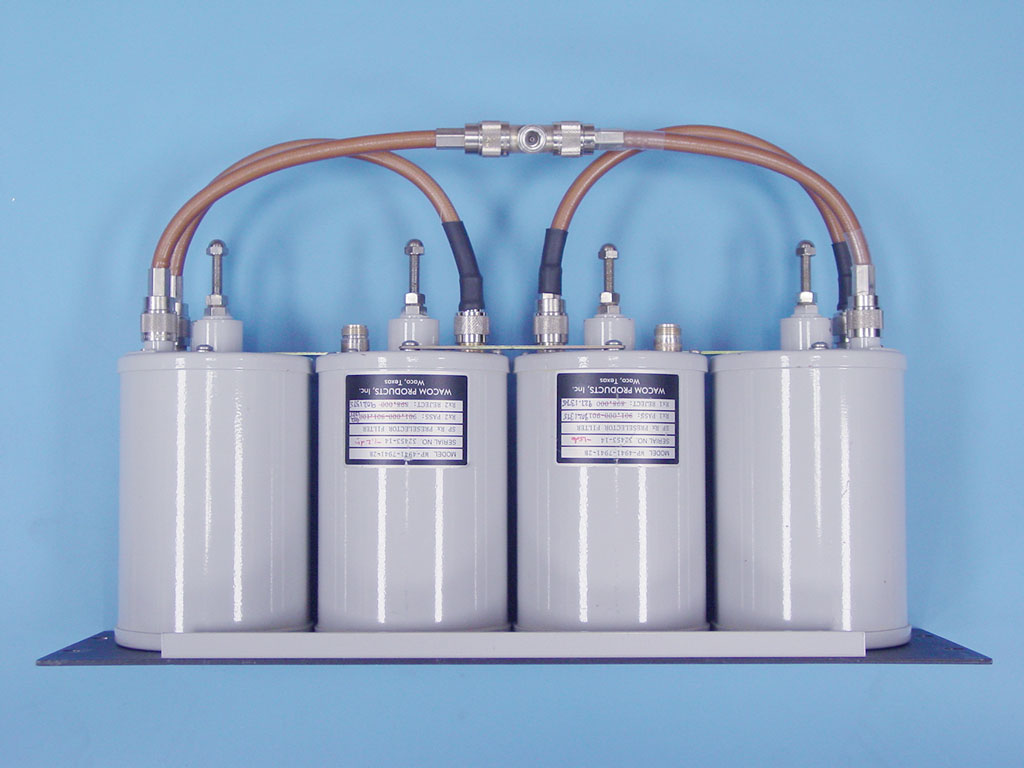
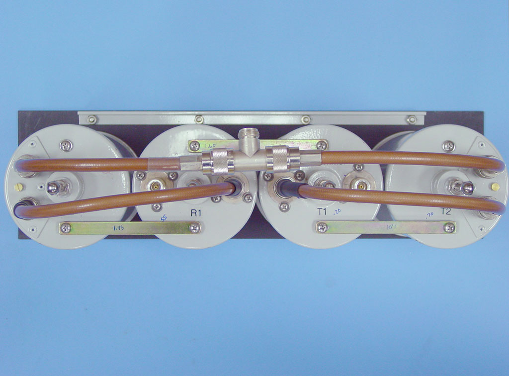
To convert the receive panel to a duplexer, the filters simply need to be retuned (one pair for receive and one pair for transmit) and a coupling harness for the single antenna port needs to be constructed. I originally left the RG142 cable in place for coupling between the two cavities in each pair (performance was good with original 8.375" length) and fabricated the bridle between the receiver and transmit sides using UT141 (RG402) semi-rigid cable. This was chosen to simplify the determination of proper lengths on each side of the Tee connector.

When the repeater output power was increased to 90 watts, the coupling cables were changed from RG142 and UT141 to the larger RG393 double shielded teflon cable. The original cables were adequate for the 90 watts, but after noticing some heating of the cables in the transmit path, I decided to embark on the adventure of changing the cables to larger, lower loss cable.

The photos to the left show the final configuration of the duplexer. Since the larger RG393 cable had a larger minimum bend radius than the original RG142 /UT141, I had to reorganize the layout of the filters to accommodate the larger bends of the RG393. The information on this page documents the cable fabrication and performance of the final (RG393) configuration. This link (also at the bottom of the page) points to archived data for the original RG142/UT141 configuration.


Duplexer Cable Lengths

Duplexer Cable Diagram
click for larger image (16KB)


The diagram to the left shows the cable lengths used on the N6EX repeater duplexer. These cables were made from RG393 double-shielded teflon coax. The diagram and included chart show the lengths between the two cavities (Bp and BpBr) on each side of the duplexer as well as lengths between the BpBr on each side and the Antenna Tee connector. The lengths are measured from the ends of the connectors.

Also included is a length of the cable from the receiver port of the duplexer to the input of the LNA/Filter panel. This length is a multiple of a half wavelength at 902 MHz and was selected to optimize out-of-band rejection characteristics of the entire receive filtering system.


Duplexer Tuning/Performance

The procedure used to tune the duplexer is as follows:
  1. Tune individual cavity (Bp & BpBr)
  2. Connect pair of cavities and verify performance
  3. Connect two pairs to Tee and verify performance
An Agilent E5071B series network analyzer was used to tune and measure the duplexer. The coupling loops on the receive pass cavity were left in approximately the same position as they were received, which yielded approximately 0.6 dB. The coupling loops on the transmit pass cavity were set for minimum insertion loss (about 0.2 dB).

Receive Path Performance

Receive Pass Filter Plots
click for larger image (24KB)

Receive Pass Cavity
  • Coupling loops adjusted for approx. 0.6 dB insertion loss
  • 23 dB input return loss
  • 25 dB rejection at transmit frequency


Receive Pass-Reject Cavity Plots
click for larger image (28KB)

Receive Pass-Reject Cavity
  • Approximately 0.7 dB insertion loss
  • 25 dB input return loss
  • 57 dB rejection at transmit frequency


Receive Pass + Pass-Reject Cavity Plots
click for larger image (28KB)

Combined Receive Pass + Pass Reject Cavities
  • 1.5 dB insertion loss
  • 25 dB input return loss
  • >80 dB rejection at transmit frequency


Duplexer Total Receive Path Plots
click for larger image (28KB)

Total Duplexer Receive Path (at Tee)
  • 1.6 dB insertion loss
  • 32 dB input return loss
  • >80 dB rejection at transmit frequency


Transmit Path Performance

Transmit Pass Filter Plots
click for larger image (24KB)

Transmit Pass Cavity
  • Coupling loops adjusted for approx. 0.2 dB insertion loss
  • 28 dB input return loss
  • 16 dB rejection at receive frequency


Transmit Pass-Reject Cavity Plots
click for larger image (28KB)

Transmit Pass-Reject Cavity
  • Approximately 0.7 dB insertion loss
  • 19 dB input return loss
  • 55 dB rejection at receive frequency


Transmit Pass + Pass-Reject Cavity Plots
click for larger image (28KB)

Combined Transmit Pass + Pass Reject Cavities
  • 1.0 dB insertion loss
  • 25 dB input return loss
  • 81 dB rejection at receive frequency


Duplexer Total Transmit Path Plots
click for larger image (28KB)

Total Duplexer Transmit Path (at Tee)
  • 1.2 dB insertion loss
  • 23 dB input return loss
  • >80 dB rejection at receive frequency


Original duplexer configuration (RG142 cables)

Return to Repeater Home Page