Design approach:
902-927 MHz has been a pretty unused band for many years but a recent upsurge in activity has brought us to take another look at the band. 1200 MHz was easy so 902 should be easier! Propagation is very similar to 440 MHz with a db or two more attenuation for a given antenna and power. The availability of inexpensive but reliable radios and their simple modifications where necessary makes 902 a great band for communicating especially mobile.
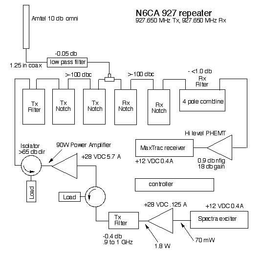
I researching out the current design trends in repeater building for 902 it was learned that more people use some type of mobile radio like a Spectra for an exciter and a modified paging transmitter driver, PURC5000 for the power amplifier. Exciters are usually lowered in power to about 7 watts to drive the PURC5000 driver amplifier to about 75 watts after removing the input amplifier.
This seemed to me to be a very inefficient way of getting to a respectable power level in light of the state-of-the-art transistors that are available today. M/A-COM RF Power Innovations makes a >50% efficient 90watt transistor, 0810-090CF that has 17.5 db of gain at 960 MHz. That means 1.6 watts of drive will yield 90 watts output.
The modified Spectra needs about 7 watts of DC power at 1.6 watts output. This means the entire repeater will need about 180 watts for 90 watts output. Not too shabby! High efficiency switching power supplies are readily available today and +28 VDC is easier to deliver (smaller wires) to the system than +12 VDC at higher currents. This 90 watt amplifier only needs a little less than 6 amps at +28 VDC.
As we get more components of this repeater assembled we will post the results on this web page so check back often. The repeater has been on the air (bench test into yagi) in one watt mode testing out the exciter, receiver and controller.
Part One: Spectra repeater exciter modifications
Part Two: 927 MHz exciter clean up filter
Part Three: 90 watt power amplifier
Part Four: MaxTrac receiver modifications
Part Five: Receiver front end band pass filter preamp assy
Part Six: Duplexer and transmit band pass filter
Part Seven: Isolator and Low pass filter
Part Eight: Complete repeater assembly