
In building this new repeater for 927 MHz it was decided to use one of the new M/A-COM RF Power Innovations power amplifier transistors. Selected was the single ended 90 watt device, 0810-090CF which has about 17+ db gain at 960 MHz and 90 watts output. This means only about 1.6 watts of drive. 50% efficiency was obtained from the 90 watt amplifier; amazing considering the terrible inefficiency of many amplifiers in use today on 902. It was also decided to replace the inefficient driver/radio power module as well. The stock drive level was also a little non standard for Spectra radios and inefficient when the power was cranked down It was decided to modify the Spectra only using its VCO output of about 70 mw. It drives a M/A-COM RF Power Innovations 960 MHz transistor, 0810-002 to about 1.6 watts. It was decided to use a +28 v transistor since the 90 watt amplifier runs on +28 VDC The new driver amplifier in the Spectra is adjusted for about 120 ma of current and will easily deliver more than 2 watts when interfaced to the Spectra.
+13 VDC current for the exciter stby = 360 ma.
+13 VDC current in transmit = 470 ma
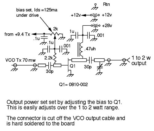
+28 VDC current in transmit = 125 ma while transmitting
Schematic diagram of added amplifier
The rear of the Spectra was machined to accommodate an SMA female connector and feed-thru capacitors instead of the "normal" Motorola connectors. ....yuk! The new amplifier was checked in every way for stabilty: voltage, load mis-match, frequency and drive level.
A combline band pass filter will be fabricated to eliminate the 1/2 & 3/2 spurs coming out of the Spectra as they are only -40 to -50 dbc. Too dirty for a mountain top exciter. Goal: > -100 dbc for these spurs into the final amplifier.
The new driver was mounted on a Duroid pc board which was compression soldered to a machined Copper block. It mechanically replaces the original power module which was removed. The unused portion of the original pc board was also removed to allow a better RF interface to the new power amplifier and make room for the new coaxial cable to the output connector. It was found that to original low pass filter and output network was too lossy to use; about 1.5 db....not good.
After mods the 463 MHZ and 1390 MHz spurs were about -40 to -50 dbc. A filter is needed.
Thanks to Gary, WA6MEM for his assistance on this project.
Copper block & ptfe board, boss protrudes thru board for soldering transistor down. Kind of a pain but do-able with a little effort.
![]()
almost completed board. Edges were wrapped with copper to bring grounds to front side.

Original Spectra with power module and driver removed.

Close up of RF portion of board. Most all components were removed from the original board.

The completed assembly. Note the removed section of the original board to allow access to the output connector area.

Output connector. Flex UT85 semi-rigid coax was used out of convenience.

Close up of the amplifier and 8 volt bias regulator and bias pot. This transistor needed more than 5 volts bias.

The modified rear of the exciter

Closeup of the machined out portions of the Spectra.