D. A. Bathker K6BLG
Summer 2004
It often becomes necessary to connect dominant mode rectangular cross-section waveguide (wg) to dominant mode circular wg with low reflection (and wg mode purity). The most common example is to connect a TE-10 rectangular wg to a TE-11 circular wg to be used for a feed on a microwave dish. In this case the wg modes have similar field patterns and a simple solution arises.
A difficult way to do this is to construct a taper of some sort, usually over a length of a few or several wavelengths, gently blending the two cross-sections. If either wg is operating near cutoff, or even towards the low end of the recommended rectangular wg band, reflections will be large and highly variable with frequency. This occurs because the taper is being forced to convert the 'input' guide wavelength (gw) to the 'output' gw (in addition to converting the impedances and slight field pattern changes). The two gw may differ greatly and give rise, in the main, to the reflections. Such gw-changing transitions are called inhomogeneous transitions.
A simple alternative is to first size one (or the other) TE waveguide to force the guide wavelengths to be equal, throughout. In the case at hand, generally, the rectangular wg is fixed by standards (e.g. WR-42, perhaps a preamp input), leaving the circular wg diameter for the feed as a variable. When the gw is uniform throughout, the (mini) wg system is called homogeneous.
Then, a simple, single-section, quarterwave (gw) impedance-and-mode-changing transition (transformer) is all that is needed for many applications. For very broadband applications as many as 4 quarterwave sections have been used, with full rectangular wg bandwidth being accommodated with low reflection (Ref.1). The modest bandwidth solution is only a quarterwave in length while the broadband solution is but one wavelength in length, far better than a typical taper and usually better performing as well.
Let us design a simple single-section quarterwave transformer, to connect WR-42 to a TE-11 mode wg feed. We adopt 24.192 GHz as the center frequency
The first principle is to size the circular wg to match the rectangular wg gw. This means the cutoff wavelengths must be equal. Once that is done, the TE gw's will track (be equal) with frequency, any frequency.
The second principle comes to us from old coaxial practice (coaxial being a homogeneous "wg" given a uniform dielectric constant throughout). The second principle is the familiar quarterwave impedance matching section Z' = sqrt (Zin x Zout). This works for coaxial as we all know, and it works for homogeneous hollow wg's as well.
Lambda-c (cutoff wl) for TE-10 rectangular 'guide is (lambda-c = 2a) with (a) being the width of the 'guide. Lambda-c for circular 'guide (TE-11 mode) is (lambda-c = 2 Pi r/1.84118...) where Pi is 3.14159..., r is the radius of the circular 'guide and the 1.84118... well, that's a Bessell Function root; it's just wrapped up in the physics of the matter and we won't be intimidated by that.
We next set the two cutoff equations to be equal; 2a = 2Pi r/1.84118. In other words, for any "a" (rectangular wg width), there is a corresponding "r" (circular, TE11 mode wg radius) that forces the 'guide cutoff wl equality and hence the 'guide wl tracking &endash; the homogeneous solution. In the case of WR-42 (a = 0.420 inches) the corresponding circular 'guide radius is 0.246 inches. (Do the arithmetic). This ensures the wanted behavior and note, the size of the required circular guide is a bit larger than you may be used to; here, for WR-42 we must use 0.492 inch diameter.
All we have to do then is to design the intermediate matching section. Now, the equation for TE-mode impedance* (either rectangular or circular cross-section) is given by Zo = 2b/a, where b is the height and a is the width of the rectangular 'guide and b = a = 2r for the circular TE-11 'guide (!). In other words, for WR-42 (b = 0.420 inches, a = 0.210 inches) Zo = 1.000 (relative) (at any frequency) and for a circular 'guide of radius 0.246 inches Zo = 2.000 (relative) (at any frequency). This is true for any frequency in either 'guide.
This is the "secret" of the whole matter of connecting these two 'guides ... the impedance ratio is always two (2), whenever their cutoff wl (and therefore their tracking 'guide wavelengths) are equal.
Then by our old coaxial knowledge, the single quarterwave transformer necessary to connect these two 'guides should have an impedance of [(sq-rt) ( Zin*Zout)] = 1.414Zo. (sq-rt 2Zo). Knowing that Zo = 2b/a, for all 3 of these TE 'guides, we can confidently say 2b/a = 1.414, or b/a = 0.7071, then b (the quarterwave section) = sq rt (0.210 x 0.492) = 0.321 inches and a = b/0.7071 = 0.455 inches. (Do the arithmetic).
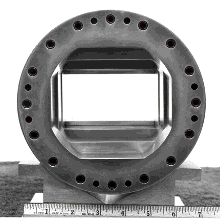
So, to connect the rectangular WR-42 to a circular TE-11 'guide (of diameter 0.492 inches) one needs a 'simple' short quarterwave (gw) section of specially machined 'guide, having the dimensions of a = 0.455 inches by b = 0.321 inches, the corners of which are to be truncated by the 0.492 inch diameter. Thus, the matching transformer cross-section is a hybrid of rectangular and circular 'guides but with specific impedance level (1.414 relative).
The length of the matching transformer must be a quarterwave long in guide wl at the frequency needed. For 24.192 GHz the TE 'guide wl (for any and all of the three wg's) is very close to 0.600 inch. A quarter guide wl is therefore 0.150 inch. Because E-plane steps dominate in this design (respectively 0.055 and 0.086 inches, one-sided) with the H-plane steps being so small (each is only 0.018 inch, one-sided) and because E-plane steps introduce a shunt capacitance (just as in coaxial lines) the final transformer length needs to be about 95% of the true quarterwave gw, or 0.142 inches.
To preserve mode purity (the TE-11 "output") it is recommended such "simple" transitions be highly mechanically symmetric (up-down, and sideways) to a few thousandths of an inch, to prevent higher-order waveguide modes to be excited, particularly near the higher end of the (rectangular standard recommended) wg band. Likewise, the feed itself, with slightly large input diameter needs to be sensibly symmetric as well.
Note: I have built and used several of such transformers in the 900 and 1200 MHz and 3.7-4.2, 7-8 and 11.7-12.2 GHz bands with good results. No more long, disappointing tapers for me. You too, I suggest.
I have tried to clarify this description of a simple-minded process, which has been found to be not so simple to describe after all. Anyone with questions, criticisms or comments should contact the author &endash; K6BLG, Box 23 La Canada, CA, 91012. Good microwaving Gents.....
Dan A. Bathker K6BLG JPL (Ret.)
*Power-Voltage definition to be exact, but it doesn't matter if we are consistent (and we are).
Ref: IEEE Trans. MTT, Feb. 1967 pp. 128-130
4-Section Homogeneous Transformer WR-430 to WC-504
(2.150 x 4.300 to 5.040 inch diam) 1.7-2.6 GHz VSWR Max = 1.05
(To illustrate a, b, and the corner radii)