Web Version :10-8-2001
Modifying the Qualcomm "Texas" Synthesizer with Dual LO
Capability
for 2304/2401 MHz Operation
By Ed Munn, W6OYJ
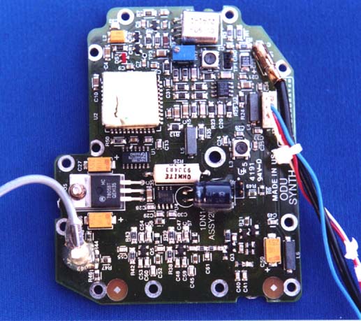
One of the early pieces of surplus Qualcomm hardware that became widely available for use and modification by radio amateurs is unofficially known as the "Texas" synthesizer due to the shape of its PC board layout. See Figure 1. This synthesizer board features the Qualcomm 3036 synthesizer chip, a square 44-pin IC that is capable of phase-locking an external (on the board) microwave voltage-controlled oscillator (VCO) to an external (off-the-board) precision 10.00 MHz reference crystal oscillator. This mid-2 GHz synthesizer has been widely used with an external X4 multiplier as the heart of synthesized local oscillator/transverters supporting amateur operation at 10,368 MHz. Also, although not discussed in earlier amateur radio modifications, the board includes a support IC (U-1) that enables easy external switching of the synthesizer between two preset VCO frequencies. Such a capability is currently of interest for amateur cw/ssb operation at 2304 MHz and AO-40 Satellite downlink reception at 2401 MHz.
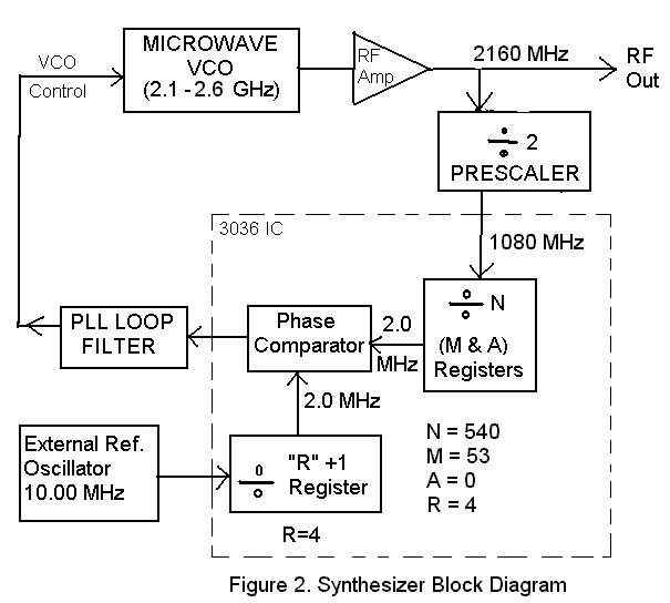
The VCO operates in the range between 2.1 and 2.6 GHz. with an output power of about +14 dBm. The synthesizer can phase-lock the VCO to a discrete frequency according to the values set into three registers contained in the 3036 chip. See Figure 2. The R register acts to divide the external 10 MHz reference frequency by a value of (R+1) to produce the internal Phase Lock Loop (PLL) frequency. This is one of two signals applied to a phase comparator in the 3036 chip. If R is set to 9, then the PLL frequency will be the reference divided by (R+1) or 10.00 / (9+1) = 1.00 MHz. The original wiring of the synthesizer boards set the R register to 1, for a PLL of 5.00 MHz. R can have any value from 0 to 15. Most amateur radio modifications have utilized a PLL frequency of 5, 2 or 1 MHz.
The second signal applied to the internal phase comparator is derived from a sample of the VCO output. The 3036 synthesizer chip cannot process an input signal as high in frequency as the 2 GHz VCO's range, so part of the VCO output is divided by 2 in a prescaler and then applied to the 3036 chip. This ( VCO / 2 ) signal is then further divided in the 3036 chip by two registers ( M and A ) set to produce a division ratio of N. When that signal exactly matches the frequency and phase of the reference-driven PLL signal, the synthesizer will lock and hold the VCO in that relationship. The phase comparator output is filtered, external to the 3036 chip, to produce the control voltage for the VCO. The VCO microwave frequency, when locked, is an integer multiple of ( PLL * 2 ) and the integer is N. The values of N, M, A and R must all be integers. N must be between 90 and 1295.
Earlier modification procedures of this synthesizer described cutting the support IC (U-1) from the board so that it would not interfere with the modified hard wiring of the registers to operate on a single VCO frequency. The discovery of this U-1 function makes it possible to easily set the synthesizer to support two LO applications in different segments of a given microwave band. It seems obvious that any current modification of these units should take advantage of the potential use of U-1. This will provide a synthesizer that can be switched between two preset precision frequencies by merely grounding or leaving open an already available external wire. This article will describe a modification for use as a dual LO source for operation in the 2.3-2.4 GHz amateur band.
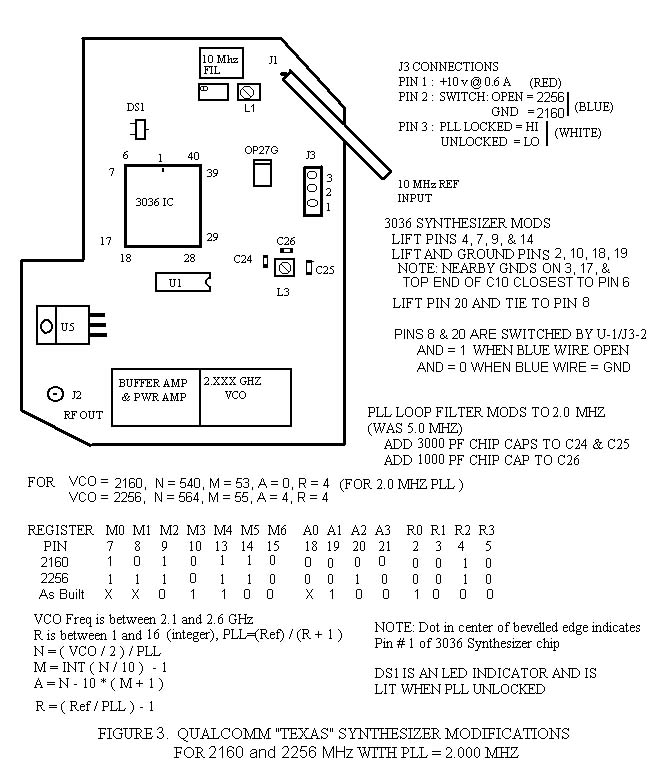
Before describing the details of this modification, other features of the "Texas" board need to be explained. See Figure 3. The 3036 chip is an early version and has high power consumption and dissipation compared to the later 3216 and 3236 synthesizer chips. It draws about 0.6 amps at 10 volts and must be heat-sinked. This is done by a rubbery heat-conducting square pad attached to the top of the chip and designed to contact the original metal lid of the synthesizer's shielded compartment. You should plan to use a shielded enclosure with a similar means of conductively carrying off the 3036 heat. Also on the synthesizer board is a buffer/power amplifier which raises the 2 GHz VCO output power to about +14 dBm, a 5-volt regulator (U5), a 10 MHz crystal filter which filters the external reference input, and a PLL loop filter which includes C24, C25, C26, and L3 as seen on Figure 3. This filter has initial values suitable for the 5 MHz original PLL frequency, and must be modified if the PLL is changed to other values. The filter's purpose is to greatly reduce spurious outputs occurring in the VCO output, and spaced from the carrier by multiples of the PLL frequency.
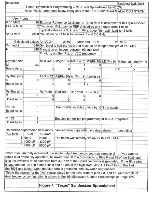
Now to planning the modification. One VCO frequency we want is a 2160 MHz LO to support cw/ssb operation at 2304 MHz with an i.f. frequency of 144 MHz. The other LO frequency needed is 2256 MHz for AO-40 satellite reception at 2401 MHz with an i.f. of 145 MHz. Now we need to see if they can both be supported by this synthesizer board. Fortunately, Kerry Banke, N6IZW developed an interactive spreadsheet, in Excel 97 format to help determine the acceptable values of N, M, A, and R for a given set of PLL and VCO frequencies. The spreadsheet also shows the required state for each of the register pins of the 3036 chip. Figure 4 shows the spreadsheet results for a VCO frequency of 2160 MHz with a 2 MHz PLL. The values of N=540, M=53, A=0, and R=4 are produced, along with the appropriate synthesizer pin states. If you have other frequencies of interest, this interactive spreadsheet can be downloaded from the web site of the San Bernardino Microwave Society at the URL described in Reference 5. If you don't have access to Excel to use the spreadsheet, the synthesizer equations are shown in the lower left part of Figure 3.
Using the spreadsheet again for a VCO frequency of 2256 and PLL of 2, produces values of N=564, M=55, A=4, and R=4. Furthermore we know that 2 MHz is the highest frequency PLL available to us that will work within the possibilities of the R register. A 5 MHz PLL will not work because the VCO output would have to be at integral multiples of ( 2 X 5 ) or 10 MHz., such as 2150, 2160, 2170, etc., but not at 2256 MHz. A 1.00 MHz PLL could work, but analysis indicates that the LO phase noise would be increased by 6 dB compared to a PLL of 2.00 MHz.
Refer again to Figure 3. Near the bottom I have summarized the required states of the register pins for 2160 and 2256 MHz, and the original (as built) PC board setup. The modification for amateur use involves lifting certain register pins to set a high (1) state, or lifting others from the PC board and then grounding them to set a low (0) state. Many of the pins are left untouched because they are already in the correct state.
The hard-wired programming modifications consists of gently cutting synthesizer Pins 4, 7, 9, and 14 where they emerge from the PC board and lifting them clear to assume the high (1) state. Then cut and lift Pins 2, 10, 18 and 19, and tie them to nearby grounds as described in Figure 3. A steady hand, a magnifying lens, and a sharp-pointed Exacto knife are needed for this process. Finally, only two of the synthesizer pins need to be "soft-wired" so they can be toggled between 0 and 1 to shift the VCO between the two desired frequencies. They are Pins 8, and 20. As U-1 Pin 6 is already connected to Pin 8, it is only necessary to cut and lift Pin 20 and tie it to Pin 8. To tie two pins together, take a fine wire (single strand of zip-cord wire) and tack solder the lifted pin to the desired pin on the chip. The same approach is used for the pins that need to be grounded
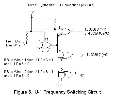
It may help to look at the original (as-built) circuit configuration of U-1 and its connection to the synthesizer chip as seen in Figure 5. As described above, the blue wire on J3-2 controls the U-1 chip to toggle between frequencies. If you only want to use the synthesizer for 2160 MHz, then just permanently ground the end of the blue wire. The white wire on J3-3 provides an external indication of the PLL Lock State. PLL Locked = HI, Unlocked = LO.
Modifying the PLL loop filter for 2.00 MHz requires "piggybacking" additional chip capacitance on top of existing capacitors C24, C25, and C26. Use a 3300 pF cap for both C24 and C25, and a 1000 pF cap for C26. Again, see Figure 3 for locations
Testing the modified synthesizer.
Now with the lid off your enclosure,
connect the 10 MHz reference oscillator and apply a regulated +10 VDC to the red
lead connected to J3. The indicator LED, DS1 on the synthesizer board should briefly
flash "on" then go out. This indicates the synthesizer is phase-locked.
As indicated in Figure 3, the output frequency should be 2256 MHz if the blue wire
on J3-2 is open, and 2160 MHz if it is grounded. The accuracy of the 2 GHz output
frequency in Hz will be the ratio of that frequency to the 10.00 MHz reference oscillator.
1 Hz error at 10 MHz will give 216 Hz error at 2.16 GHz. With a good 10.00 MHz temperature-compensated-crystal-oscillator
(TCXO) you will be much more stable than systems based on crystals in the 100 MHz
range.
Pre-testing the Synthesizer's VCO Frequency Range
Not all the synthesizers obtained from salvaged equipment will function to the frequency limits described in this article. If you have an accurate spectrum analyzer or frequency counter that covers the 2.1-2.6 GHz range, there is a useful pre-test you can make to discover the actual limits of the VCO prior to beginning modifications. To do this you should set up the synthesizer so that you can couple enough output energy from the amplified VCO to observe its frequency (remember direct output is around +14 dBm). Now locate the eight-pin OP-AMP IC marked "OP27G" near the variable inductor L1. A white line across the top indicates the Pin 1 end. Now apply 10.00 MHz from your external reference to the synthesizer and +10 VDC to the red lead connected to J3. Temporarily touch a grounded clip lead to Pin 2 of OP27G and observe the VCO output frequency. Now touch the grounded clip lead to Pin 3 of OP27G and observe the VCO frequency. These two frequencies are the limits of the VCO's control range.
More About "Soft" Wiring of the Synthesizer Pins
The particular pair of frequencies chosen for this article required that only two synthesizer pins needed to be toggled between 0 and 1 in order to shift from 2160 to 2256 MHz. Both pins needed to be set to the identical states. This was a matter of luck, because for any other pair of frequencies it would be just as likely that one or more pins would have to be switched to the opposite states as pins 8 and 20 in the above example. Refer to Figure 5 again and you will see that U-1 Pin 8, originally wired to synthesizer Pin 7, assumes the opposite state as U-1 Pin 6. So if you need to "soft" wire any pins to the opposite states, you can connect them to either U-1 Pin 8, or to synthesizer Pin 7 if it has not been cut and lifted from the PCB.
Acknowledgments
Full credit for these modifications must go to Kerry Banke, N6IZW and Chuck Houghton, WB6IGP who have spent the last several years developing the amateur microwave modification techniques for several evolutions of Qualcomm- produced equipment and subassemblies.
References
1. Web articles on Qualcomm hardware modifications can be found on the web site
of the San
Bernardino Microwave Society at http://www.ham-radio.com/sbms. Scroll
down to the section
"Technical Papers from the San Diego Microwave Group".
2. (Modifying the Qualcomm Synthesizer) in "Above & Beyond" Column,
C. L. Houghton WB6IGP,
73 Magazine, Oct. 1996, P.71
3. "A Synplexer Rig for 13 CM", Ed Munn W6OYJ, Proceedings of Microwave
Update '99 (Plano,
Texas), October 1999, p.p. 117-126.
4. "Modifying the Qualcomm 'Texas' Synthesizer with Dual LO Capability for
2304/2401 Operation",
Ed Munn, W6OYJ, Proceedings of Microwave Update 2001"
(Sunnyvale, California), September 2001,
p.p 14-20.
5. Programming Spreadsheet for the "Texas" Synthesizer, Kerry Banke,
N6IZW.
Download this Excel 97 Spreadsheet in a zipped file
(syntexas.zip). Then unzip it and open it with
Microsoft Excel to use.