This IF system has been in operation since 1989 both here on the mainland and in Hawaii by KH6HME.
There are several important reasons for expending time and energy to build the following microwave system:
1. 28 MHz Intermediate Frequency (I.F.) using a high performance HF radio
2. Common first I.F. to minimize construction
3. All band capability
4. Avoid ham band first I.F. due to receiver interference and transmit in-band products (144 MHz)
5. Use of single high stability oscillator for each band (one crystal); compatability with frequency-west sources.
The solution to these requirements is a double conversion, single oscillator, double high side local oscillator heterodyne scheme taking advantage of the relatively high stability 'Frequency-West' sources available today. That is, if it's stable at 10 GHz it's 108 times better at 100 MHz.
Theory of Operation
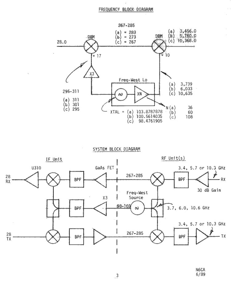
Refer to the Frequency Block Diagram.
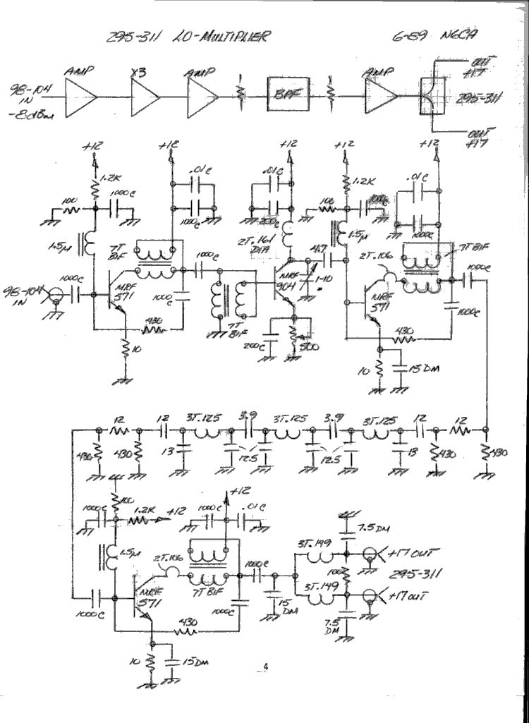
The freq-west source runs as normal. The 100 MHz oscillator test point is used to drive a LO/Multiplier board. The 100 MHz signal is attenuated, buffered, tripled to 300 MHz, filtered and amplified to drive the first I.F. Up/Down converters. This frequency scheme was chosen on the basis of spectral purity; there is very little RF from 267 to 283 MHz, generally. Adequate first I.F. and microwave L.O. separation are also provided. Simple filters provide good second I.F. filtering (28 MHz) and LO (295-311 MHz) and image attenuation.
Refer to System Block Diagram.
Once the basic IF unit is constructed, additional bands can be added by building RF units. Reasonably rapid band changing is accomplished by changing RF units and cabling; less than one minute from actual experience.
Construction
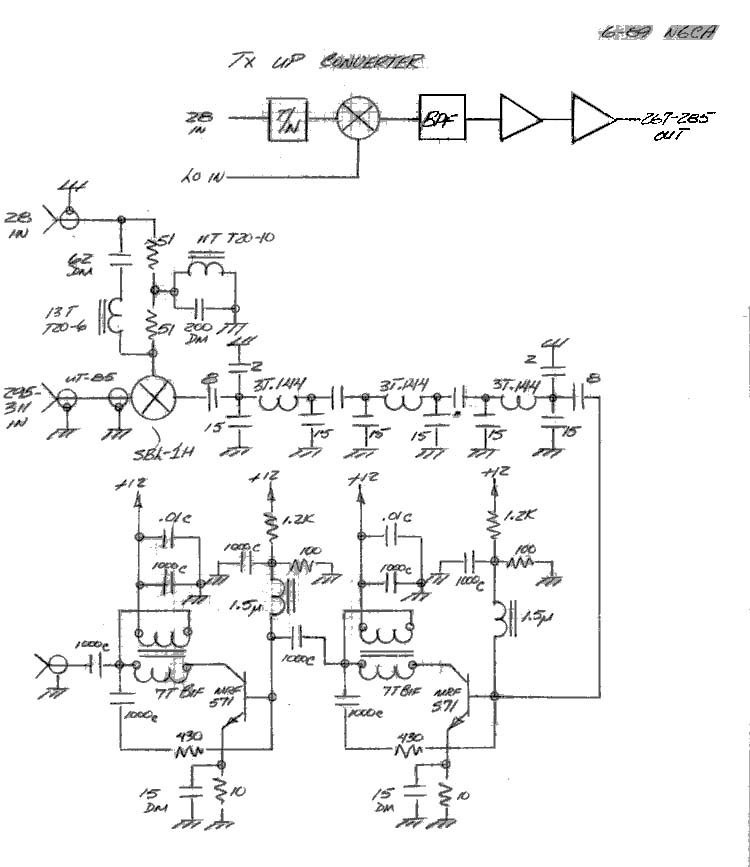
The Up/Down converter consists of three boards, each housed in an aluminum box. Interconnections between boxes are SMA but BNC's will work. Coaxial connections to the entire assembly are BNC for each cable changing especially when attempting rapid band changing.
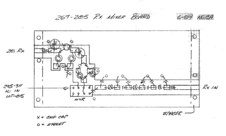
All boards are double-sided FR-4, .062 inch thick with full ground on all backsides. All boards are mounted into boxes using 1/16" aluminum sheet spacers under each end of the board. This provides adequate RF returns, solid mounting and clearance for the eyelets on the backside. All grounds are via eyelets, .062 Dia, soldered to both sides of board.
Components are all mounted to the top side of the boards for simplicity. The (Double Balanced Mixer) DBM's mount through a square hole in the board and are tack-soldered to both sides. The DBM's mount with the pins sticking up and connections to the pins are made with #24 buss wire. All pins must be connected; signal or ground. Both IF port pins must be connected together.
All air coils are #24 GA buss wire and are adjusted by bending. Use a wooden stick.
Feed-thru semi-rigid coax is used to bring the 295-311 LO signal to each dBm in the Up/Down converters. High level dBm's (+17 ) are used for better dynamic range.
All band pass filter capacitors are dipped Mica. Do not change these values. Use ± .5 pf max tolerance capacitors, or better yet measure and select.
The MRF571 transistors are inexpensive (1$) and will provide better linearity and higher output power than most MMIC's.
All transformers are broadband using high permeability cores (> 4000) and use 50 Ohm #28 GA Bifilar wire (7 turns).
Alignment
All circuits are unconditionally stable including the LO-Multiplier. Under conditions of varying load, drive, frequency and supply voltage, stability is maintained. The feedback power amplifiers are inherently stable by design as well.
Align all BPF's by isolating from circuit; small coax temporarily attached works well. Sweep and tune each filter for best average return loss in a 50 Ohm system. Tune filters by slight bending of coils.
Adjust the 50 Ohm pot in the X3 multiplier for maximum output. It can then be replaced with a fixed resistor.
The termination networks on the I.F. ports of the DBM's don't need to be tuned. They improve the linearity of the DBM's.
The TX Up converter will provide better than &endash;70 dBc IM3 at 0 dBm output which is more than needed for the microwave DBM's by several dB. Do all level adjustments at 28 MHz.
The 100 MHz oscillator test point is sensitive to load changes and its level should be measured on each oscillator and the appropriate 50_ attenuator installed to achieve a level of about &endash;8 dBm at the input to the LO-Multiplier.
Thanks to K6ELQ and the Texas microwave guys for the assistance.
73 N6CA