I find a quadrature multipath monitor to be a much more effective multipath indicator than an oscilloscope display. But a scope lets you monitor multipath while listening to normal audio, so it can be handy at times.
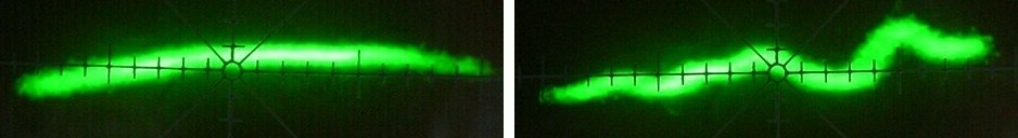
These images show multipath-free and multipath-laden traces with my antenna pointed directly at a station and with it pointed at nearby hills. The broad curvature is due to the IF filter. The wiggles are due to multipath.
A multipath scope displays the envelope of the IF signal on the vertical axis with the detected composite signal driving the horizontal axis. The horizontal axis corresponds to instantaneous frequency. When an FM signal propagates by more than one path, the time delay between paths changes the phase of the combined signal with frequency, distorting the detected audio. The path interference also causes peaks and dips in the IF-signal envelope; the signal contains AM as well as PM components. A multipath display shows the AM component.
I added multipath outputs to my Sony ST-S555ES in a way that should be possible with any tuner. I used the wideband detector output for the horizontal signal and the IF-chip signal-meter output for the vertical. If you AC-couple the vertical signal at the scope, you won't need to recenter the trace when the signal level changes. DC-couple the horizontal signal so you can examine the IF response when mistuned.
This is an application circuit for the Sanyo LA1235 IF chip. The S-meter output on pin 13 follows the incoming signal strength. Its logarithmic response makes relative changes mostly independent of absolute signal level. Although the output will saturate on very strong signals and sensitivity varies somewhat with signal level as shown below, it would take a fair amount of circuitry to outdo this simple indicator.
Proper filtering of the S-meter output is important. If too heavily filtered, the vertical signal will not respond quickly enough to track the horizontal signal, smearing the trace. If too lightly filtered, out-of-band power will fuzz the trace. Resistive loading matters, too. If too lightly loaded, the output will slew-rate limit into a capacitive load due to the current-source drive. If too heavily loaded, you may exceed the output current spec (2 mA for the LA1235). I used a 6.2kΩ pulldown resistor and paralleled it with a .01 µF ceramic disk capacitor that measured .008 µF. Response was noticeably worse with .015 µF, so it pays to experiment. I fed the output cable through a series 3.3kΩ resistor to add some protection.
I took the horizontal signal from the wideband op-amp that follows the ST-S555ES detector. Directly attaching a capacitive cable to a high-impedance detector can severely degrade stereo separation. Add an op-amp buffer if necessary. A 1kΩ resistor in series with the output offers some protection against external hazards. I found that extracting the horizontal signal after the tuner's complex postdetection filter smeared the scope trace. The filter added way too much time delay.
I also tried a more linear filter, moving the capacitor to the output. This did not work as well, smearing the trace more for the same out-of-band rejection. Again, I think it might pay to experiment with your particular IF chip. The S-meter output isn't used in the ST-S555ES and the pin floats. When used it's likely to have a capacitance of .022 µF or greater attached. You may need to reduce the capacitance or isolate the pin with a resistor and pick off the multipath output there, where you can properly filter the signal for the scope trace.
 88–108 MHz