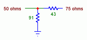
Most signal generators have an output impedance of 50Ω. To avoid unanticipated effects when aligning an FM tuner or measuring its performance, it's best to transform this to 75Ω.

A simple minimum-loss pad provides a broadband match. Use chip resistors or the shortest possible lead lengths to minimize stray inductance and pickup of local broadcast signals. Loss is 5.6 dB for the 5% values shown. For calibrated voltage output, set the signal generator to 1.55 times the desired output level in microvolts. (For 1% resistors, use 43.2Ω and 86.6Ω. Loss is 5.7 dB.)
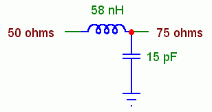
An L-network is nearly lossless. This circuit isn't broadband like a minimum-loss pad, but it easily covers 88–108 MHz.
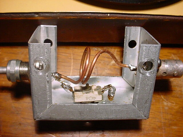
This shows an L-network in a small metal box. The inductor is made of #14 wire and the capacitor is a small mica trimmer. I adjusted the turns spacing and the trimmer for best return loss over the FM band. Response must be checked with the box cover in place.
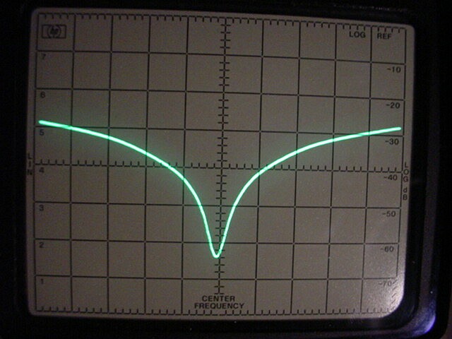
This shows the return loss of the L-network with a coaxial 75Ω load from 88 to 108 MHz. I used an HP 141T/8553B/8552B spectrum analyzer, 8443A tracking generator, and Anzac THV-50 power splitter. The return loss of the power splitter with a 50Ω load was a constant 30 dB across the FM band. This is the limit of the test setup. Results beyond this figure indicate cancellation of the residual return loss.
The L-network loss measured 0.05 dB. For calibrated voltage output, set the generator to 0.83 times the desired output level in microvolts.
A twelfth-wave transformer can match 50Ω to 75Ω with negligible loss and no adjustment. It is a special case of a series-section transformer.
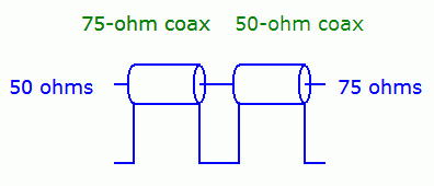
The transformer consists of a 75Ω coax section in series with a 50Ω section, each about 1⁄12-wavelength long. At 98 MHz the section length for solid-dielectric coax with a velocity factor of 0.66 is 6½″. For foam dielectric at 0.83, it is 8⅛″. For best accuracy, obtain the manufacturer's specified velocity factor for your cable. Then use the twelfth-wave transformer calculator to find the section lengths and to analyze performance over the FM band.
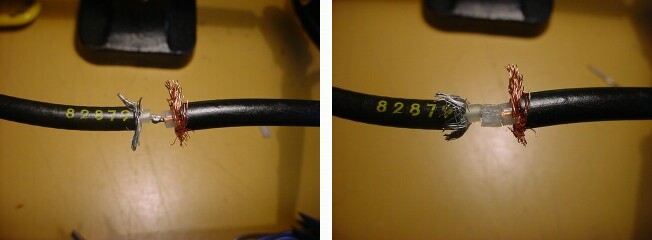
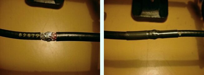
To splice the sections, cut the cable jackets back ¼″, strip the dielectric ⅛″, overlap the center conductors, and solder them. Place a ⅛″ piece of slit dielectric over the joint, put a dab of superglue in the slit, overlap the shields, and solder them. Cover the splice with heat-shrink tubing.
For lab use, install a BNC connector on the 75Ω cable and an F-connector on the 50Ω cable. I assume the impedance changes ½″ from the end of the BNC and ¼″ from the end of the F. When cutting the cables, account for this, for the center-conductor length each connector requires, and for the splice overlap, which effectively shortens the 75Ω section ⅛″.
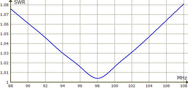
This shows SWR for a twelfth-wave transformer cut for 98 MHz.
Like the L-network, the twelfth-wave transformer loss measured 0.05 dB. For calibrated voltage output, set the generator to 0.83 times the desired output level in microvolts.
Vacuum tube tuners provide 300Ω antenna terminals. They may connect to a balanced RF transformer with a floating or grounded centertap, or to an unbalanced input circuit with one terminal grounded. For a grounded centertap, connect a 50:75Ω matching network to one antenna terminal and nearby chassis ground. For an unbalanced input, use the following matching network. Use it also for a balanced floating input by grounding one antenna terminal.
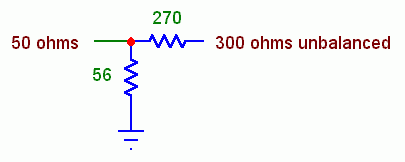
Loss is 13.3 dB. For calibrated voltage output, set the generator to 1.88 times the desired output level in microvolts.
 88–108 MHz