It's difficult to make a Yagi perform well over the entire 88–108 MHz band. Multiple driven elements or multiple reflectors are necessary for really good performance. But if bandwidth is restricted, a simple design with excellent performance is possible. I optimized this ten-element Yagi for 88–92 MHz. The boom length is 239″.
I optimized the design with the AO 9.57 Antenna Optimizer. The red dot marks the 75Ω feedpoint.
Calculated performance is for 28 analysis segments per conductor halfwave. Forward gain includes mismatch and conductor losses. F/R is the ratio of forward power to that of the worst backlobe in the rear half-plane.
Frequency  Impedance    SWR   Mismatch  Conductor   Forward     F/R
   MHz        ohms             Loss dB   Loss dB   Gain dBd      dB
   88.0   55.8 + j0.1   1.34     0.09      0.04      10.23     34.60
   88.5   63.1 + j2.3   1.19     0.03      0.05      10.45     35.03
   89.0   72.1 + j3.2   1.06     0.00      0.05      10.63     35.72
   89.5   81.9 + j1.1   1.09     0.01      0.06      10.75     36.57
   90.0   90.6 - j3.8   1.21     0.04      0.07      10.82     37.07
   90.5   95.3 - j10.0  1.31     0.08      0.08      10.85     36.00
   91.0   96.1 - j13.0  1.34     0.09      0.10      10.85     35.36
   91.5   91.9 - j10.8  1.27     0.06      0.13      10.81     37.61
   92.0   75.5 + j12.1  1.18     0.03      0.21      10.65     36.30
High-Performance Yagi for 88-92 MHz
Free Space Symmetric
88 89 90 91 92 MHz
10 6061-T6 wires, inches
x1 = 0
x2 = 21.51948
x3 = 25.15592
x4 = 31.62797
x5 = 43.00666
x6 = 74.83947
x7 = 114.956
x8 = 156.0457
x9 = 197.848
x10 = 238.5
y1 = 33.8256
y2 = 34.86547
y3 = 31.27198
y4 = 30.20728
y5 = 29.57982
y6 = 29.03308
y7 = 28.81374
y8 = 28.46262
y9 = 27.87227
y10 = 25.14078
1  x1  -y1  0   x1  y1  0    0.375
1  x2  -y2  0   x2  y2  0    0.375
1  x3  -y3  0   x3  y3  0    0.375
1  x4  -y4  0   x4  y4  0    0.375
1  x5  -y5  0   x5  y5  0    0.375
1  x6  -y6  0   x6  y6  0    0.375
1  x7  -y7  0   x7  y7  0    0.375
1  x8  -y8  0   x8  y8  0    0.375
1  x9  -y9  0   x9  y9  0    0.375
1 x10 -y10  0  x10 y10  0    0.375
1 source
c = 26.23784
Wire 2, center c pF
Use ⅜″ tubing. Dimensions are valid only for isolated elements (nonconductive boom or insulated mounts). The matching network is the lowpass equivalent of a hairpin match. Split the driven element leaving a gap no larger than ¼″, solder a 27 pF capacitor across the feedpoint, and feed with 75Ω coax. Use a current choke at the feedpoint.
The following table shows the change in average performance over 88, 89, 90, 91, and 92 MHz in dB when altering a single dimension by ⅛″ (1⁄16″ for element half-lengths and 5% for c).
Symbol    Gain    F/R
    x1    0.00   0.03
    x2    0.01   0.25
    x3    0.01   0.17
    x4    0.00   0.07
    x5    0.00   0.09
    x6    0.00   0.12
    x7    0.00   0.17
    x8    0.00   0.24
    x9    0.00   0.14
   x10    0.00   0.06
    y1    0.00   0.10
    y2    0.00   0.05
    y3    0.02   0.33
    y4    0.01   0.11
    y5    0.00   0.27
    y6    0.01   0.86
    y7    0.00   1.10
    y8    0.01   0.97
    y9    0.00   0.64
   y10    0.00   0.20
     c    0.00   0.00
This design uses seven elements on a 119″ boom. The matching capacitance is the same.
Frequency  Impedance    SWR   Mismatch  Conductor   Forward    F/R
   MHz        ohms             Loss dB   Loss dB   Gain dBd     dB
   88.0   55.2 - j4.6   1.37     0.11      0.03      7.89     29.07
   88.5   60.9 - j2.7   1.24     0.05      0.04      8.05     29.22
   89.0   68.2 - j1.7   1.10     0.01      0.04      8.18     29.33
   89.5   75.8 - j2.3   1.03     0.00      0.05      8.29     29.48
   90.0   83.4 - j4.1   1.13     0.02      0.05      8.36     30.18
   90.5   89.1 - j6.7   1.21     0.04      0.06      8.40     30.36
   91.0   91.3 - j6.8   1.24     0.05      0.07      8.44     30.00
   91.5   91.6 + j2.6   1.22     0.04      0.09      8.46     29.68
   92.0   98.8 + j32.4  1.59     0.23      0.12      8.24     29.43
Antenna file:
Shorter Yagi for 88-92 MHz
Free Space Symmetric
88 89 90 91 92 MHz
7 6061-T6 wires, inches
x1 = 0
x2 = 18.76155
x3 = 23.45349
x4 = 29.27525
x5 = 45.385
x6 = 79.87294
x7 = 118.5
y1 = 33.55704
y2 = 34.45306
y3 = 30.9235
y4 = 29.94886
y5 = 29.50708
y6 = 28.5225
y7 = 26.48781
1  x1  -y1  0   x1  y1  0    0.375
1  x2  -y2  0   x2  y2  0    0.375
1  x3  -y3  0   x3  y3  0    0.375
1  x4  -y4  0   x4  y4  0    0.375
1  x5  -y5  0   x5  y5  0    0.375
1  x6  -y6  0   x6  y6  0    0.375
1  x7  -y7  0   x7  y7  0    0.375
1 source
c = 26.21472
Wire 2, center c pF
Sensitivity analysis:
Symbol    Gain    F/R
    x1    0.00   0.02
    x2    0.01   0.02
    x3    0.01   0.09
    x4    0.01   0.13
    x5    0.00   0.04
    x6    0.00   0.06
    x7    0.00   0.06
    y1    0.00   0.10
    y2    0.00   0.01
    y3    0.04   0.37
    y4    0.00   0.04
    y5    0.01   0.60
    y6    0.02   0.44
    y7    0.01   0.09
     c    0.00   0.00
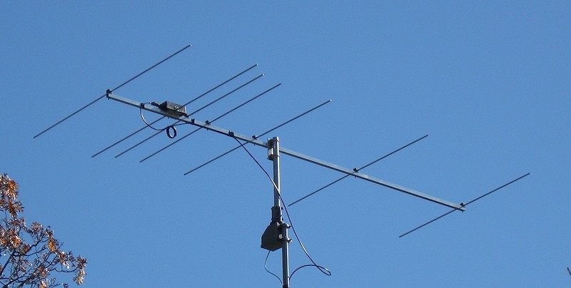
Joe Hageli built an earlier version of the ten-footer in Spring Grove, Illinois.
 88–108 MHz